Tractor performance
Power losses occur when transmitting engine power through the drive wheels, the PTO shaft, and the hydraulic system. If Flywheel power is known, multiply it by 0.9 to estimate PTO power.
Drawbar power is the power transferred through the drive wheels or tracks to move the tractor and implement. You can estimate Drawbar power by multiplying the PTO power by the appropriate value from the table below:
| Tractor Type | Concrete | Firm Soil | Tilled Soil | Soft Soil |
|---|---|---|---|---|
| 2 wheel drive | 0.87 | 0.72 | 0.67 | 0.55 |
| Front wheel assist | 0.87 | 0.77 | 0.73 | 0.65 |
| 4 wheel drive | 0.88 | 0.78 | 0.75 | 0.70 |
| Tracks | 0.88 | 0.79 | 0.80 | 0.78 |
Slippage of drive wheels on soil surfaces is a power loss. Travel reduction, or slip (s), is calculated from:
S = ((An - A1)/An) * 100
where:
- S is slip, percent;
- An is the advance under no load conditions per wheel or track revolution,
m(ft);
- A1 is the advance under actual load conditions per wheel or track revolution, m(ft).
Tractive efficiency (TE) is the ratio of drawbar power to axle power and can be estimated when slip is known. TE (and hence tire efficiency) of a wheel can be predicted using a series of equations that take into account tire dimensions, soil conditions, slip, etc. Tractor performance is calculated by summing the individual wheel performances. Maximum TE is obtained with slip ranges of:
4-8% for concrete;
8-10% for firm soil;
11-13% for tilled soil;
14-16% for soft soils and sands.
Implement (machine) power requirements
Draft (D) is the total force parallel to the direction of travel that is required to pull the implement. Both functional draft (soil and crop resistance) and draft required to overcome rolling resistance of the implement are included.
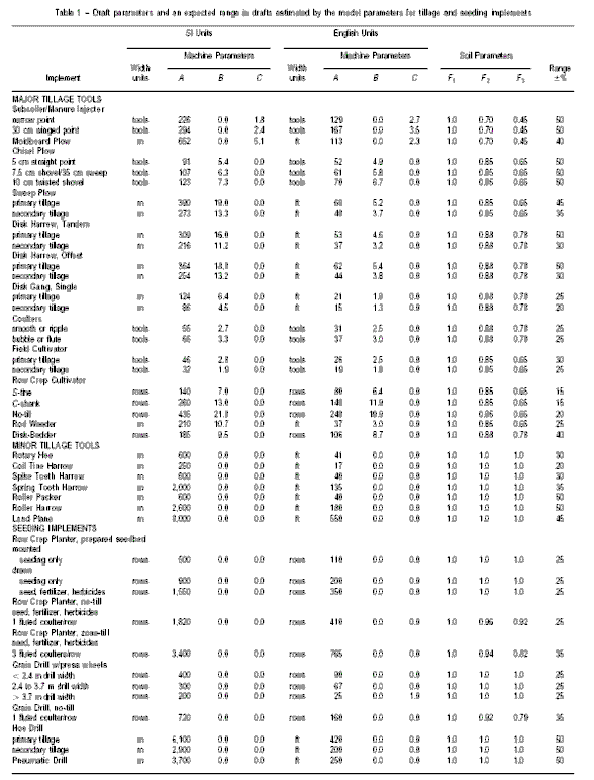
Draft force required to pull many seeding implements and minor tillage tools operated at shallow depths is primarily a function of the width of the implement and the speed at which it is pulled. For tillage tools operated at deeper depths, draft also depends upon soil texture, depth, and geometry of the tool. Typical draft requirements can be calculated as:
D = F*I [ A + B + C(S)2] W*T
where:
- D is implement draft, N (lbf);
- F is a dimensionless soil texture adjustment parameter (table 1);
- i = 1 for fine, 2 for medium and 3 for coarse textured soils;
- A, B and C are machine-specific parameters (table 1);
- S is field speed, km/h (mile/h).
- W is machine width, m (ft) or number of rows or tools (table 1);
- T is tillage depth, cm (in.) for major tools, or equals one for minor tillage tools and seeding implements.
(PDF version of this table,
11KB)

Motion resistance becomes appreciable when heavy implements are used in soft or loose soils. Tire parameters and wheel loadings must be known or assumed to calculate this value. Total implement motion resistance is computed as the sum of the individual wheel values.
Drawbar power for tractor-powered implements (and propulsion power for self-propelled implements) is computed as:
Pdb = Ds / 3.6
where:
- Pdb is drawbar power required for the implement, kW;
- D is implement draft, kN;
- s is travel speed, km/h;
or,
Pdb = Ds / 375
where:
- Pdb is drawbar power required for the implement, hp;
- D is implement draft, lb;
- s is travel speed, mph.
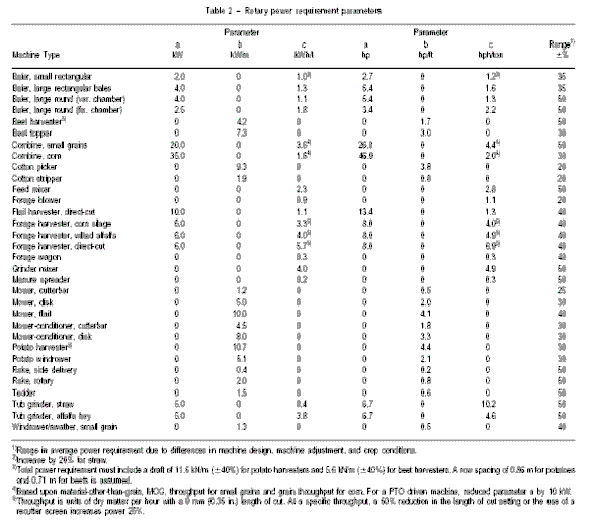
Power-takeoff (PTO) power is power required by the implement from the PTO shaft of the tractor or engine. Typical PTO power requirements can be determined using rotary power requirement parameters available from a number of sources. Implement power take-off power can be calculated as
Ppto = a + bw + cF
where:
- Ppto is power-takeoff power required by the implement kW (hp);
- w is implement working width, m (ft);
- F is material feed rate, t/h(ton/h) wet basis;
- a, b, and c are machine specific parameters (Table 2)
(PDF version of this table,
8KB)
Hydraulic power is the fluid power required by the implement from the hydraulic system of the tractor or engine. Implements hydraulic power can be computed as
Phyd = pF/1000
where:
- Phyd is hydraulic power required by the implement, kW;
- F is fluid flow, L/s;
- p is fluid pressure, kPa;
or,
Phyd = pF/1714
where:
- Phyd is hydraulic power required by the implement, hp;
- F is fluid flow gal/min;
- p is fluid pressure, psi.
Electric power is required to operate components of some implements. To compute implement electric power
Pel = IE/1000
where:
- Pel is electric power required by the implement, kW;
- I is electric current, A;
- E is electric potential, V;
or,
Pel = IE/746
where:
- Pel is electric power required by the implement, hp;
- I is electric current, A;
- E is electric potential, V;
Total power requirement for operating implements (drawn or selfpropelled) is the sum of implement power components converted to equivalent PTO power. Total implement power requirement can be computed as
PT = (Pdb/ EmEt) + Ppto + Phyd + Pel
where:
- PT is total implement power requirement, kW (hp);
- Et is traction efficiency (expressed as a decimal);
- Pdb is drawbar power required for the implement, kW (hp);
- Phyd is hydraulic power required by the implement, kW (hp);
- Ppto is power-takeoff power required by the implement, kW (hp);
- Pel is electric power required by the implement, kW (hp);
- Em is mechanical efficiency of the transmission and power train.
- This coefficient is typically 0.96 for tractors with gear transmissions.
NOTE: Additional power is required to accelerate and overcome changes in topography, soil and crop conditions. Additional power is also required for operator-related equipment such as hydraulic control systems, air conditioning, etc.
Field machine performance
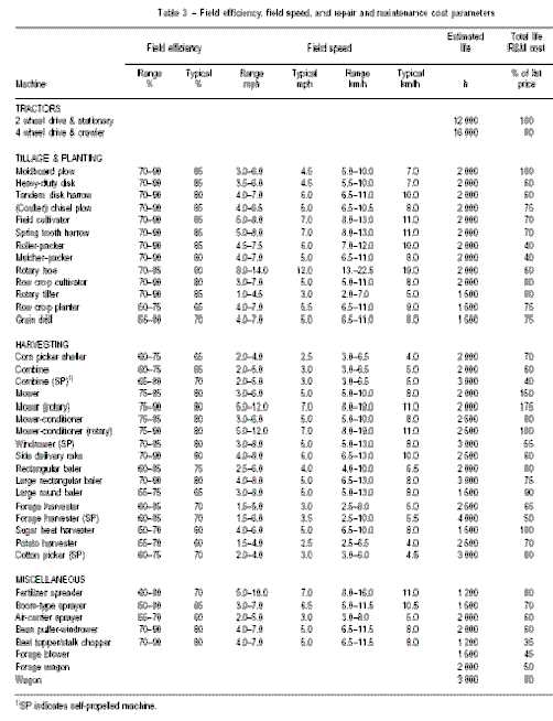
Field efficiency is the ratio between the productivity of a machine under field conditions and the theoretical maximum productivity. Field efficiency accounts for failure to utilize the theoretical operating width of the machine; time lost because of operator capability and habits and operating policy; and field characteristics. Travel to and from a field, major repairs, preventive maintenance, and daily service activities are not included in field time or field efficiency. Field efficiency is not a constant for a particular machine, but varies with the size and shape of the field, pattern of field operation, crop yield, moisture, and crop conditions. The following activities account for the majority of time lost in the field:
turning and idle travel;
materials handling;seed;
fertilizer;
chemicals;
water;
harvested material;cleaning clogged equipment;
machine adjustment;
lubrication and refueling (besides daily service);
waiting for other machines.
Effective field capacity is a function of field speed, machine working width, field efficiency, and unit yield of the field. Area capacity is expressed as
Ca = swEf/10
where:
- Ca is area capacity, ha/h;
- s is field speed, km/h;
- w is implement working width, m;
- Ef is field efficiency, decimal;
or,
Ca = swEf/8.25
where:
- Ca is area capacity, acre/h;
- s is field speed, mile/h;
- w is implement working width, ft;
- Ef is field efficiency, decimal.
NOTE: Typical ranges of field efficiency and field speed can be found in Table 3.
(PDF version of this table,
6KB)

Material capacity is expressed as
Cm = swyEf/10
where:
- Cm is material capacity, t/h;
- s is field speed, km/h;
- w is implement working width, m;
- Ef is field efficiency, decimal;
- y is unit yield of the field, t/ha;
or,
Cm = swyEf/8.25
where:
- Cm is material capacity, ton/acre;
- s is field speed, mile/h;
- w is implement working width, ft;
- Ef is field efficiency decimal.
- y is unit yield of the field, ton/acre.
NOTE: Typical ranges of field efficiency and field speed can be found in Table 3.
This information in this document was adapted from American Society of Agricultural Engineers Standards.
Issued in furtherance of Cooperative Extension work, acts of May 8 and June 30, 1914, in cooperation with the U.S. Department of Agriculture, James A. Christenson, Director Cooperative Extension, College of Agriculture and Life Sciences, The University of Arizona.
The University of Arizona is an equal opportunity, affirmative action institution. The University does not discriminate on the basis of race, color, religion, sex, national origin, age, disability, veteran status, or sexual orientation in its programs and activities.
Any products, services, or organizations that are
mentioned, shown, or indirectly implied in this web document do not imply
endorsement by The University of Arizona.
Information provided by:
Wayne E. Coates wcoates@u.arizona.edu, Research Professor, Arid Lands
College of Agriculture and Life Sciences, The University of Arizona
Revised July 2002.
Crop Mgmt | Soil Mgmt | Irrigation | Varieties | Cotton Comments
Home | Cotton | Advisories
document located at: http://cals.arizona.edu/crops/equipment/agmachinerymgt.html
Copyright © 2001 University of Arizona,
College of Agriculture and Life Sciences
Webmaster: Al Fournier (acis@ag.arizona.edu)